
Your new add on battery kit comes with all of the parts needed to install this kit onto a Roadster V2, V3, or CF Racer1 model bike. You will not use all of the parts that came in the kit and will only need to use the parts required for the model that you own. This guide will go over installing and using the add on battery kit on a Ride1Up Roadster V3 model bike.
Before we install this kit onto your bike lets go over some of the basics of this add on battery and how the system works. The battery itself has a few different buttons on the bottom that all have different functions
- The battery charge port can be found under the rubber cover. This battery will have to be charged separately from the in frame battery and uses the same charger as the bike (second charger included in the kit).
- The battery will have to be plugged into the bike through this plug. The wire side of the plug screws onto the battery for a secure connection.
- The power button will turn the battery on and off. The battery is on when the button is depressed and off when the button is raised.
- When pressed, this button will tell you the charge state of the battery. Blue is above 90%, green is 50-90%, red is 20-50%, and flashing red is below 20%. The charge indicator will only work when the battery is turned on.
- This USB port can charge devices when the battery is turned on.

Once the battery is installed, charged, and turned on, the system will automatically pull power from whichever battery is more charged, or both if equally charged, and there is nothing required by the rider to activate the system. There is no indicator on the display showing the add on battery is active and the only way you will know the system is working is that the battery will drain much slower and you will be able to ride much further. It is that simple!
Now that you know how the system work, let's get into how you can install this kit onto your Roadster V3.
Step 1- Loosen Motor Cable
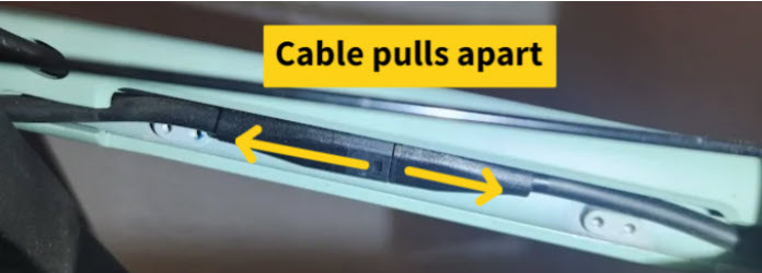
The controller needs to be removed to plug in your new battery balancer. The motor will need to be unplugged in order to allow for enough slack in the cables to remove the controller from the bike. To do this, remove the motor cable cover located on the inside of the chainstay of the frame by loosening the four small hex bolts. Once the cover is removed the motor cable can be pulled apart and the zip tie holding the cables in place can be cut.


Step 2- Access The Motor Controller
Once the motor cable is loose the controller can be removed from the frame. This can be done by loosening the lower battery panel in the frame by removing the two Torx 20 bolts in the frame. Once the bolts are removed the lower battery panel can be slid out of the frame. After the panel is out, the controller can be lifted out of the bicycle and the yellow XT30 battery connection can be unplugged. Good practice is to take a picture of how the wires are arranged with the controller inside the frame, so that it can be recalled later during reinstallation.


Step 3- Route the New Wiring
Now that the guts of the bike are exposed we can start to install the new parts into the bike. Take the end of the new wiring that has the two small yellow XT30 connectors and push them up through the hole in front of the bottom bracket toward the motor controller. Plug the corresponding electrical connections into the bikes motor controller and battery panel.


Step 4- Reinstall the Motor Controller and Battery Panel
Now the motor controller can be installed back into the bike. This is most easily done by ensuring that all of the wires sit above or below the motor controller to give you the most room possible as shown below.

Use the new Torx 20 bolts included in your kit to install the black balancer cover box using the same holes that hold the battery panel inside your frame. At this point you can go ahead and plug the motor back into the controller and secure the wiring cover back onto the chainstay of the frame.

Step 5- Install the Battery Balancer
You can now plug in the brains of this system which is the battery balancer. Plug the three labeled XT60 connectors into their corresponding connectors on the new wiring. Once plugged in, the balancer can be installed into the black housing using the 4 small Phillips head screws and the top cover plate.

Here are a few tips that may help with installing the balancer into its housing.
- Install the balancer so that it sits above the three yellow XT60 connectors to prevent the parts from rattling in the housing.
- Push all of the colored wires into the housing for the best fit.
- Install the cover plate with the hole closest to the frame and push the extra length of wires through the hole near the bottom bracket.


Step 6 - Install the Add on Battery
All that is left to do is install the add on battery mount to the water bottle frame mounting point. Ensure that the wiring to the add on battery is properly secured with Zip ties to keep it safely away from the cranks, chainring, and rear wheel.


Now you are ready to ride your Roadster V3 with added range! Feel free to reach out to our team with photos if you have any trouble with this process.


